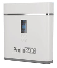
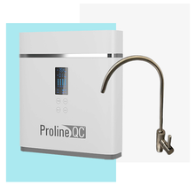
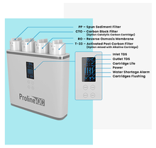
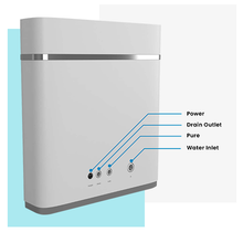
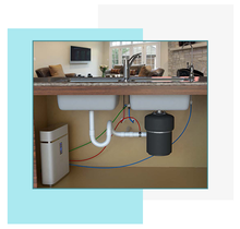
Easy Filter cartridge
Clear digital display
moniter cartridge life
System flushing, extends the
life of the filter cartridges
Quick Connect back ports
for no-hassle installations
Owners Manual/Installation Guide
Product and Accessories


Main Body

Four Filter Cartridges
Includes spun PP filter(PP), block carbon filter (CTO), reverse osmosis membrane (RO) and post activated carbon filter (T-33).

One Accessory Box
Includes faucet, 3-way ball valve, three pieces of tubing, instruction book. adapter and drain clamp. Reference Images for Accessories.

Faucet

Faucet connector

3-WaybaHvave

3 Colored tubing (red, blue and green)

Instruction book

Transformer

Drain clamp
Technical Specifications and Water Treatment Process Process Flow Diagram
Technical Specifications
Feed water quality: Municipal tap water
Voltage and frequency: 100-240V, 50/60Hz
Power input: 24V
Purified water flow: .35 gal/min
Feed water temperature: 45-110F°
Feed-water TDS: * 250ppm
Feed-water Chlorine level: S 0.2ppm
Rejection: 90-99%
Feed-water pressure: 15-60psi
Electric shock resistance: type 2
Water Treatment Process Flow Diagram
Technological process

Diagram

Installation Schematic Diagram

Installation
Tapping Into The Cold Water Line
(Using the water supply adapter 3-way ball valve)
For flex metal or plastic line.
NOTE: QC-RO system must be connected to the COLD water supply only.
1) Turn off the cold water supply to the sink faucet by locating are round or oblong handle and turning clockwise until the water supply is off.
NOTE: If the cold water shut off valve fails to turn off the water, the house supply can be turned off at the main water supply.
2) The water supply adapter may be installed at the faucet connection.
3) Disconnect the 3/8” flex line from the base of cold water basin supply angle stop valve.
4) Re-connect the 3/8” 3-way ball valve to the basin supply angle stop valve.
5) Re-connect flex line to the 3-way ball valve .
6) Push green tubbinp in to Ouick Connect fitting up to tube stop. Pull on the tubing to check it is secure. Test the system before use.
NOTE: All local plumbing codes must be followed to ensure proper installation and use of your system.
CAUTON: A pressure regulator is recommended for feedwater pressure above 60esi.

Tools Required:
1) Hand drill for faucet hole. Use the appropriate bit for the surface you are drilling. [1/2“ for non air gap faucets and - 7/8” drill bit for air gap ones).
A) Titanium bit for metal sinks•
B) Glass and tile bit or Relton cutter for porcelain sinks.
C) Diamond core it for granite.
2) Phillips head screwdriver.
3) Adjustable crescent wrench.
4) Basin wrench.
5) 1/2” drill bit for drain clamp.
3) For Porcelain Sink: Before starting the drill motor, apply firm downward perssure on the bit until a crunching occurs. This will help keep the drill from moving when starting the hole. Use a special porcelain hole cutter.
4) For Stainless Steel Sink: Before using the selected bit, an indent should be made with a center puch to keep the drill bit from moving. A samll pilot hole will also aid the drill process.
5) For best results, keep steady firm prssure while drilling the hole. Too little pressure during the start will cause excess wear on the it and progress will be slow.
6) Once the hole is complete, clean the area of metal chips and roughness around the hole. Metal chips will stain porcelain.
Warning: it is highly recommended for granite slate countertops, to use the assistance of a licensed professional to drill the hole for the faucet. Serious damage can occur to the counter if done by an inexperienced person.
Drilling the hole for the faucet
NOTE: SAFETY GLASSES SHOULD BE WORN TO PROTECT YOUR EYES WHILE DRILLING THE FAUCET WHOLE.
1) For best results, a 1/2” drill bit for a non air gap faucet or 7/8” dill bit for an air gap faucet should be used to drill a hole into your sink for the auxiliary faucet.
2) Carefully select the faucet location making sure it will have a neat water fall pattern and that the faucet stud will be accessile from below once the whole is completed.
Mounting The Facuet
Standard Faucet
1) Drill a 1/2" hole in the sink or the counter top, or use an existing hole.
2) Slide chrome cover plate and rubber gasket on to stem of faucet and place faucet onto sink, with the stem going through the hole.
3) Place metal slotted washer over threaded stem of faucet.
4) Tighten nut from under the counter surface to lock the faucet into place.
5) Thread the faucet connector onto threaded stem of faucet. Do not use Teflon tape.
6) Connect blue 3/8” tubing to faucet connector.

Air Gap Faucet (Optional)
1) Drill a 7/8” hole in the sink or the counter top, or use an existing hole.
2) Slide chrome cover plate and rubber gasket on to stem of faucet and place faucet onto sink, with the stem going through the hole.
3) Place metal slotted washer over threaded stem of faucet.
4) Place plastic spacer over threaded stem of faucet locking in place, slotted washer onto countertop.
5) Tighten nut from under the counter surface to lock the faucet into place.
6) Attach red 1/4” drain water discharge line to DRAIN INPUT barb. And red 3/8” drain line to DRAIN OUTPUT oarb as shown.
7) Thread the faucet connector onto threaded stem of faucet. Do not use Teflon tape.
8) Connect blue 3/8” tubing to faucet connector.

Compression Connections
A compression fitting may be found with the faucet. To make the connections, slide a compression nut onto the tubing. Slip the white plastic sleeve onto thetubing with the beveled end towards the end of the tubing. Insert a brass or plastic insert into the tubing, bottom the tubing into the fitting, slide the nut up and tighten with a wrench. DO NOT OVER TIGHTEN. Do not use the brass sleeves on plastic tubing, use only plastic sleeves on plastic tubing.

Drain Clamp Installation
1) The drain clamp assembly should be installed above the trap and on the vertical or horizontal tail piece.

2) Mark the hole position on the pipe and drill a 1/4” hole through one side of the pipe. Be careful not to drill the hole through both sides of the pipe.


3) Affix gasket provided with the drain clamp onto inside of clamp piece matching the holes. The center hole on the gasket must be removed.
4) Make sure to align drain saddle to drilled hole. Attach drain clamp to drain pipe and tighten the two screws evenly.
5) Connect the 1/4” red tubing to the drain clamp (or 3/8“ when air gap faucet is used).
Positioning The System
1) The head assembly will stand up in the sink cabinet or can be hung on screws.
2) The storage tank may be laid on its side. The bladder tank will function in both a horizontal or vertical position.
3) The head assembly and/or storage tank may be placed up to 10 feet from the point of use with some pressure loss.
EZ Fittings-Ouick Connect
Your QC-RO system is equipped with EZ fittings. The quick connect fittings feature leak proof installations. EZ Fittings provide efficient quick connection and disconnection resulting in reduction of service time and labor cost.

Cut tubing square
Cut the tube square. It is essential that the outside diameter be free of score marks and that burrs and sharp edges be removed before inserting into fittings. For soft thin walled plastic tubing, we recommend the use of a tube insert.

Insert tube
Fitting grips before it seals. Ensure tube is pushed into the tube stop.

Push up to the tube stop
Push the tube into the tube stop. The collet (gripper) has stainless steel teeth which hold the tube firmly in position while the o-ring provides a permanent leak proof seal.

Pull to check scure
Pull on the tube to check that it is secure. It is a good practice to test the system prior to leaving site and/or before use.

To disconnect ensure the system is depressurized before removing the tube. Push in collect squarely against face of fitting, With the collect held in the position, the tube can be removed. The fitting can there be re-used.
First Use Instruction
1) Connect RO system to the transformer. The oower indicator will come on, and you will hear three chimes, the machine will flush for 90 seconds while flushing icon blinks.
2) When the system starts filtering water you will see the computer display real-time TDS numbers, the cartridge life span and power indicator will light on. AU LED display icons turn off when water tank is full.
3) When the water storage icon flash and the systems chime 10 times, the system has insufficient water or low water pressure. The machine will flush for S seconds once it has enough water or water pressure has been restored.
4) If the system stops producing water and has been operating for 6 continues hours, or if it detects a water leak, all icons will start flashing and you will hear the system chime 30 times.
Note: Under normal operation, please run water for 10-15 minutes in order for the cartrioges to flush when the system is used for the first time.
Cartridges Replacement
Cartridge reminder

There are 6 LED indicators to show the current lifespan of corresponding cartidge filter. All cubes extinguish when filter's lifespan is over.
Note:
1. Actual lifespan of filters can be influenced by areas, water quality, seasons and daily water consumption, so the period of filters replacement may vary.
2. Please replace regularly.
Recommended Replacement Period for Cartridges
|
STAGES |
FILTER CARTRIDGE |
FUNCTION |
LIFESPAN (FOR REFERENCE ONLY) |
|
The first stage
|
Spun PP filter
|
Removes larger suspended particles in water
|
3-12 months
|
|
The Second stage
|
Black carbon filer CTO
|
Further removes organics, chlorine, odor and turbidity
|
3-12 months
|
|
The Third stage
|
RO membrane
|
Removes bacteria, heavy metals, dissolved matters and salinity
|
1-3 year
|
|
The fourth stage
|
Post Carbon filter T33
|
Adjust the taste of purified water
|
3-12 months
|
Cartridges Reset
Keep pressing Select button for 3 seconds to enter selection mode, then press Select to select the cartridge which needs to be replaced and then press Reset button.
The LED indicators shows full again. The selection mode will exit automatically if there is no operation in 5 seconds.
Please cut off the water and turn off the power before replacing cartridges.
1) Open the cap.
2) Hold the cartridge handle and ro.ate 90°counterclockwise, then pull it out.

3) Replace it with new cartridge and alipn the arrow label to” ”and rotate 90°clockwise to “ ”.

Cover the cap after finishing replacement. (The cap is unable to cover when cartridges are not in right place.)

Trouble Shooting
|
Problem |
Cause |
Solution |
|
Water pump is out service and system does not work
|
Insufficient feed water pressure
No power or power failure High pressure switch is out of order Pump is blocked and adapter fuse burn-out |
Increase feed water pressure
Power-on Replace high pressure switch Replace adaptor and repair water pump |
|
High TDS value
|
TDS of feed water is too high or system is placed long term being unused.
Cartridge lifespan is over |
Open the faucet to draw off the pure water for a while.
Cartridge lifespan is over |
|
Water pump works but system does not work
|
RO membrane is blocked
Water pump pressure loss Flush solenoid valve is damaged |
Replace RO membrane
Repair water pump Replace flush soleniod valve |
|
Constanly running water in downtime
|
Inlet water solenoid valve damaged
|
replace feed water solenoid valve
|
|
Cannot stop working when pressure tanks is full or repetitive starting
|
High pressure switch is damaged
Check valve is damaged |
Repair or replace high pressure switch
Replace Check valve |
it is highly recommended to have a water treatment profesional do all trouble shooting and repairs, with the exception of filter replacements.
Precautions for Use
Attention
1. Flush and replace cartridges regularly.
2. Do not disassemble parts randomly, it may cause water leak or damage the system.
3. Do not use a power supply that does not have the rated voltage.
4. Please pull the power plug and cut off the feed water valve for long term storage.
5. Do not store or operate in an environment of 32F° or below.
6. Handle with care when discharging, moving and installing.
Reminder
1. If you home experiences the “water hammer phenomenon*”, turn off the feed water supply to the unit immediately. Letting this hydraulic shock continue may lead to leakage or damage to the filters and filter housings. Our company does not take responsibili for any damages to the system or for leaks caused by this situation.
2. Please cut off power and source water at once in case troubles occur and ask a professional for assistance.
3. It is normal to hear some vibration sounds when system is producing water.
*Hydraulic shock, commonly known as water hammer or fluid hammer, is a pressure surge or wave caused when a fluid (water), in motion is forced to stop or change direction suddenly; a momentum Change. This phenomenon commonly occurs when a valve closes suddenly at an end of a pipeline system, and a pressure wave propagates in the pipe. It sounds like hammering in your water pipes.


